
What Is Precision Machining? Tolerances, Processes, and 5-Axis CNC Explained
Compare CNC turning, milling, and grinding by IT grade, surface roughness, and GD&T, see how 5-axis differs from mill-turn, and check what to include in a machining RFQ
Understand precision machining tolerances, surface finish, turning, milling, grinding, and 5-axis CNC, and learn what to include in a machining RFQ so suppliers can quote accurately.

Written by the JFS Steel Technical Team | Last updated: November 20, 2026
A request for "precision machining" might mean a tolerance of ±0.05 mm (±0.002 in) to one buyer and ±0.005 mm (±0.0002 in) to another. Without exact numbers, a machine shop cannot reliably select a process, plan inspection, or prepare an accurate quotation.
Precision is defined by the features that affect fit, movement, sealing, alignment, and service life. A complete drawing may specify dimensional tolerances, geometrical tolerances, surface roughness, material condition, heat treatment, and inspection requirements.
This guide explains how to read those requirements, compares CNC turning, milling, grinding, 5-axis, and mill-turn machining, and shows what engineers and buyers should include in a machining RFQ.
What Is Precision Machining?
Precision machining is the controlled removal of material to produce parts that meet specified dimensional, geometrical, and surface requirements. It may involve CNC turning, milling, drilling, grinding, or several of these processes in sequence.
There is no universal tolerance at which machining becomes "precision machining." A tolerance that is demanding for a long, thin-walled component may be routine for a short, rigid shaft. Material, part size, geometry, heat treatment, fixturing, production quantity, and inspection method all affect what can be achieved consistently.
Machine specifications are only one part of the answer. A machine may show excellent positioning performance under test conditions, yet the finished part can still be affected by tool wear, cutting force, temperature, clamping deformation, datum selection, and measurement uncertainty.
Three groups of requirements define whether a machined part is acceptable:
| Specification | What it controls | Examples |
|---|---|---|
| Dimensional tolerance | Permitted variation in size | Shaft diameter, bore diameter, thickness |
| Geometrical tolerance | Form, orientation, location, and runout | Roundness, flatness, perpendicularity, position, runout |
| Surface roughness | Fine surface texture | Ra on bearing, sliding, or sealing surfaces |
A dimension can be within its size tolerance while the part still fails roundness, runout, flatness, or surface requirements. These specifications work together and cannot replace one another.

Figure 1. Three ways to specify precision: dimensional tolerance, geometrical tolerance, and surface roughness (deviation exaggerated)
How to Read Machining Tolerances and Surface Finish
Bilateral Tolerances, Total Tolerance Width, and IT Grades
A bilateral tolerance of ±0.01 mm permits the dimension to vary by 0.01 mm in either direction, so its total tolerance width is 0.02 mm:
Upper limit − lower limit = total tolerance width
In US customary units, ±0.01 mm is about ±0.0004 in, and a 0.02 mm total width is about 0.0008 in. Converted inch values are approximate; manufacturing and inspection should follow the unit system stated on the drawing, not rounded conversions.

Figure 2. Bilateral tolerance and total tolerance width: ±0.01 mm = 0.02 mm total width
ISO 286-1 defines International Tolerance grades IT01, IT0, and IT1 through IT18. A lower IT number means a narrower tolerance width, and within the same grade the permitted width increases with nominal size.1 For a nominal diameter of 50 mm (1.97 in), the widths are:1
| IT grade | IT5 | IT6 | IT7 | IT8 | IT9 | IT10 | IT11 |
|---|---|---|---|---|---|---|---|
| Total tolerance width (mm) | 0.011 | 0.016 | 0.025 | 0.039 | 0.062 | 0.100 | 0.160 |
| Approx. (in) | 0.0004 | 0.0006 | 0.0010 | 0.0015 | 0.0024 | 0.0039 | 0.0063 |
An IT grade gives only the tolerance width. It does not define where that width lies relative to the nominal dimension. A total width of 0.025 mm could be written as +0.025/0 mm, 0/−0.025 mm, or about ±0.0125 mm. Designations such as H7, h7, and js7 combine the IT grade with the position of the tolerance zone, and the capital and lowercase letters distinguish hole and shaft zones.

Figure 3. IT5–IT11 tolerance widths at Φ50 mm (ISO 286-1)
GD&T: Size Alone Does Not Guarantee Function
Geometrical tolerancing controls characteristics that a size tolerance cannot fully describe. ISO 1101 provides the ISO GPS framework for geometrical tolerancing.2 Drawings produced for the US market may instead specify ASME Y14.5, currently the 2018 edition, reaffirmed in 2024.3
The applicable system and revision should be identified on the drawing or in the purchasing specification. ISO GPS and ASME Y14.5 share many symbols, but their rules, defaults, and interpretation should not be assumed to be identical.
Common requirements include:
- Roundness for individual circular cross-sections
- Cylindricity for the form of a complete cylindrical surface
- Flatness for mounting and sealing faces
- Perpendicularity between related features
- Position for holes and other located features
- Circular or total runout for rotating surfaces relative to a datum axis
Coaxiality, concentricity, and runout also describe different controls. Coaxiality relates a feature axis to another axis or a datum axis, concentricity concerns derived center points, and circular runout is measured on a surface while the part rotates about a datum axis. The correct characteristic depends on the functional requirement and the drawing standard, so an RFQ should include the drawing datums and feature control frames rather than a general "concentricity" value.
Surface Roughness: Why a Lower Ra Is Not Always Better
Ra is the arithmetic mean deviation of a surface profile and is usually stated in micrometers. ISO 21920-2 defines profile surface texture terms and parameters and replaced ISO 4287 in 2021.4 Useful conversions are Ra 3.2 µm ≈ 125 µin, Ra 1.6 µm ≈ 63 µin, Ra 0.8 µm ≈ 32 µin, and Ra 0.4 µm ≈ 16 µin.

Figure 4. Ra: average deviation of the profile from the mean line (illustrative)
A lower Ra generally requires more controlled machining or an additional finishing step, which adds time and cost. It is also not automatically better for every function. Some sliding or lubricated surfaces need a texture that retains lubricant, and coated surfaces need enough texture for adhesion.5 Sealing surfaces depend on the seal design, contact material, pressure, and direction of the machining lay.
Ra is an average and does not describe waviness; a surface can be smooth yet wavy.5 Two surfaces with the same Ra can also differ in peak shape, valleys, direction, or isolated defects, so Ra should be specified together with the functional requirement when surface performance matters.
What If a Drawing Does Not Specify a Tolerance?
First check the title block, general notes, purchasing specification, and any referenced customer standards.
Both ISO general tolerance standards have been revised. ISO 2768:2026, published in November 2026, replaced ISO 2768-1:1989 for the general specification of tolerance limits for linear and angular sizes.6 ISO 22081:2021 replaced ISO 2768-2:1989 for general geometrical specifications and general size specifications.7 Older drawings may still reference the withdrawn standards, because each drawing remains controlled by its stated revision and contractual requirements. A newer standard should not be applied to an older drawing automatically.
Under ISO 2768-1:1989 class m, a size over 30 mm up to 120 mm carries ±0.3 mm.8 At 50 mm, that is a total width of 0.6 mm (0.024 in), 24 times the IT7 width of 0.025 mm. Any feature that needs precision should carry its own tolerance.
Drawings from Japanese design systems may reference JIS B 0405 for general dimensional tolerances or JIS B 0419 for general geometrical tolerances.9 These should also be applied according to the class and edition stated on the controlled drawing. If the drawing, purchase order, and existing agreements specify no general tolerance system, the buyer and supplier should agree on one before quotation or production.
CNC Turning vs. Milling vs. Grinding
The result each process can achieve depends on the machine, tooling, workpiece, material, setup, and inspection strategy. The Ra ranges below are typical references for finishing operations, not guaranteed limits for every part.5

Figure 5. CNC turning, milling, and grinding
| Process | Typical finishing Ra | Main characteristics controlled | Typical parts and features |
|---|---|---|---|
| CNC turning | 0.4–3.2 µm (16–125 µin) | Diameter, bore size, roundness | Shafts, bushings, sleeves, flanges |
| CNC milling | 0.8–3.2 µm (32–125 µin) | Flatness, perpendicularity, hole location | Plates, brackets, fixtures, housings |
| Grinding | 0.1–1.6 µm (4–63 µin) | Size, form, and surface texture after heat treatment | Bearing journals, critical diameters, precision faces |
CNC Turning for Rotational Parts
In turning, the workpiece rotates while the cutting tool feeds along or across it. The process produces outside diameters, bores, faces, grooves, tapers, and threads, and most shafts, sleeves, bushings, and flanges begin here.
Accuracy depends on the workpiece length-to-diameter ratio, material hardness, chucking method, tailstock or steady-rest support, cutting conditions, and tool wear. A long, slender shaft may deflect under cutting forces, and a thin-walled sleeve can deform while clamped and spring back after release. A drawing review should account for both effects.
CNC Milling for Faces, Pockets, and Hole Patterns
Milling uses a rotating cutting tool to create faces, slots, pockets, contours, and holes on mounting plates, fixtures, brackets, machine bases, and housings, as well as flats and keyways on shafts.
Flatness, perpendicularity, and hole-to-hole relationships depend on the datum strategy and setup sequence as well as the machine. Long tool overhang reduces rigidity, and repeated reclamping can introduce datum-transfer error. When several related features must be controlled from the same datum, machining them in one setup reduces accumulated positioning variation.
Grinding for Hardened Parts and Critical Surfaces
Grinding removes a relatively small amount of material with an abrasive wheel. External cylindrical, internal, and surface grinding are used to finish critical features after turning, milling, or heat treatment.
Heat treatment can change size, straightness, and roundness,10 so machining stock is often left on critical surfaces before heat treatment and removed by grinding afterward. Grinding can control size, form, and surface texture. Polishing mainly changes surface texture or appearance and does not necessarily correct dimensional or geometrical error.
A tight dimensional tolerance does not always require grinding. Under suitable conditions, precision turning or milling may produce the specified size. Grinding becomes more likely when the part is hardened or also requires fine roughness, demanding roundness, or improved dimensional stability.
What Do 5-Axis CNC and Mill-Turn Machining Add?
5-Axis and Mill-Turn Are Different Capabilities
A 5-axis machine has three linear axes and two rotary or tilting axes, so the cutting tool can approach the workpiece from multiple directions. Mill-turn machining integrates turning with milling, drilling, or tapping in one machine. Some mill-turn machines support simultaneous 5-axis motion, while others index a B-axis milling head to selected angles before cutting.11 In simultaneous 5-axis machining, by contrast, the tool orientation changes continuously during the cut.12
- 5-axis machining: motion and axis configuration
- Mill-turn machining: integration of turning and milling processes

Figure 6. Mill-turn machine with a B-axis milling head (schematic)
Common 5-axis configurations include:12
| Configuration | Where the rotary axes are located | Main consideration |
|---|---|---|
| Table/Table | Both rotary axes move the workpiece | Workpiece weight and rotary clearance |
| Head/Table | One axis moves the spindle head and one moves the table | Tool access and fixturing |
| Head/Head | Both rotary axes move the spindle head | Large or long workpieces that stay stationary |
No configuration is best for every part. Selection depends on workpiece size, weight, required faces, tool access, interference, and production method.

Figure 7. Three common 5-axis configurations
Why Fewer Setups Help, and What They Cannot Guarantee
Completing related features in one setup reduces datum-transfer and reclamping errors.13 It can also shorten production time and simplify work-in-process control.
A 5-axis machine does not automatically make every part more accurate. Rotary-axis positioning, thermal effects, the workpiece's distance from the center of rotation, tooling, and calibration all affect the result.14 As a geometric example, an angular error of 0.002° creates a linear deviation of about 0.017 mm (0.0007 in) at a point 500 mm (19.7 in) from the rotary center:
500 × tan 0.002° ≈ 0.017 mm
This is a hypothetical illustration of angular error amplification, not the positioning specification of any machine.

Figure 8. Angular error grows with distance from the rotary axis (geometric illustration, not a machine specification)
For parts that need only one or two accessible faces, a well-planned 3-axis process may remain the practical choice. The value of 5-axis machining shows in multi-face parts, angled holes, complex contours, and features that benefit from fewer setups.
How Part Function Drives Precision Requirements
An industry name alone does not determine a tolerance. The same semiconductor tool may contain a structural cover made to general tolerances and a positioning component that needs much tighter control.
| Application | Example parts | Main machining and inspection concerns |
|---|---|---|
| Automation and robotics | Positioning shafts, fixtures, joint housings | Fits, hole location, flatness, alignment |
| Semiconductor equipment | Platforms, precision fixtures, fluid-contact components | Surface condition, cleanliness, materials, packaging |
| Aerospace and energy | Valve bodies, connectors, complex-profile parts | Drawing characteristics, traceability, inspection records |
| Medical devices | Instrument components, fittings | Materials, process control, documentation |
| Tooling and molds | Inserts, punches, locating components | Post-heat-treatment size, fit, critical surfaces |

Figure 9. Typical acceptance focus by industry
For rotating equipment, bearing journals may need a combination of size, roundness, cylindricity, runout, and surface roughness. As one reference point, NACHI's guidance for a 50–80 mm shaft carrying JIS class 5 precision bearings calls for roundness and cylindricity of 2.5 µm (98 µin) and Ra 0.2 µm (8 µin) on the fitting surface.15 Final requirements must still reflect the bearing class, fit, load, speed, and operating conditions.
For semiconductor fluid-handling components, SEMI F19 addresses the surface condition of wetted surfaces on stainless steel components.16 Actual roughness, cleaning, inspection, and packaging requirements depend on the customer's specified standard and application.
Aerospace parts may require first article inspection (FAI) under AS9102C, which verifies drawing characteristics and records materials and special processes.17,18 This should not be confused with a general dimensional check of the first production part.
ISO 13485 sets quality management system requirements for medical device organizations,19 including controls for outsourced processes, suppliers, and traceability.20 It does not prescribe one machining tolerance for all medical components.
These standards describe quality and documentation frameworks. They do not mean every part in an industry needs micrometer-level tolerances, and mentioning them here does not imply that JFS Steel holds related certifications.
Planning the Process: An Alloy Steel Shaft Example
Consider a hypothetical 50 mm alloy steel drive shaft with a bearing journal specified at IT6. At this size, the IT6 width is 0.016 mm (0.0006 in).1 The drawing must still define the tolerance zone position or give upper and lower size limits, and the engineer and supplier should confirm roundness, runout, surface roughness, hardness, and any requirements at shoulders or fillets.
A possible process sequence:
- Confirm the material specification, delivery condition, drawing revision, and functional requirements.
- Cut the material to length and turn the outside diameters, faces, and threads.
- Mill the keyway or flats, using a setup that preserves the required datum relationships.
- Quench and temper or induction harden if required, allowing for heat treatment distortion.10
- Grind the bearing journal where needed to restore size, form, and surface finish.
- Inspect dimensions, roundness, runout, roughness, and hardness, then compile the required material and inspection records.

Figure 10. Drive shaft process flow (heat treatment and grinding are currently partner processes; in-house grinding is planned)
SCM440 may be used as the material when the drawing specifies the applicable JIS standard and delivery condition. It should not be treated as automatically interchangeable with AISI 4140 or any other grade without reviewing chemical composition, mechanical property requirements, heat treatment condition, dimensions, and customer approval.
How to Evaluate a Precision Machining Supplier
Machine Specifications Are Only Part of the Picture
ISO 230-2 defines methods for evaluating the positioning accuracy and repeatability of numerically controlled machine tool axes,21 and ISO 230-3 covers tests for thermal effects.22 These tests describe machine performance under defined conditions. They do not state the tolerance that will be achieved on every finished part.
Part accuracy is also affected by:
- Machine and spindle temperature
- Workpiece thermal expansion
- Heat treatment distortion
- Part rigidity and clamping force
- Material hardness and delivery condition
- Tool length, deflection, and wear
- Datum selection and setup sequence
- Measurement resolution, calibration, and environment
A supplier should evaluate the actual drawing rather than approve a tolerance based only on a machine brochure.
Ask How Critical Features Will Be Verified
Before placing an order, ask:
- Which features are critical to function?
- Which machining process and setup will control them?
- What datum structure will be used for machining and inspection?
- Which instruments will measure the required characteristics?
- How are material and outsourced processes traced?
- Which dimensional and material records can be supplied?
- How will production stay consistent after the initial inspection is approved?
The measurement method should suit the tolerance and the geometrical characteristic. A value is useful only when supplier and buyer agree on how it will be verified.
Precision Machining Support at JFS Steel
JFS Steel began as a special steel distributor in Taichung, Taiwan, and has expanded into cut-to-length sawing, drilling, CNC turning and milling, and machining coordination.23 Material condition, cut size, machining, heat treatment, grinding, and inspection requirements can therefore be reviewed as one production plan.
Equipment and Machining Capabilities
| Equipment | Type | Manufacturer-published specifications |
|---|---|---|
| MAZAK VARIAXIS i-700T | Simultaneous 5-axis machining center with turning capability | Φ630 mm table; max. workpiece Φ850 × 500 mm (approximately Ø33.5 × 19.7 in); max. table load 700 kg (1,543 lb), evenly distributed; A-axis tilt −120° to +30°; spindle up to 18,000 min⁻¹.24 |
| MAZAK INTEGREX j-200S NEO | Twin-spindle B-axis mill-turn machine | Max. machining diameter and length Φ500 × 910 mm (approximately Ø19.7 × 35.8 in); standard model uses 1° B-axis indexing, with 0.0001° on the high-performance model25 |
| MAZAK INTEGREX j-300 | B-axis mill-turn machine | Max. machining diameter Φ500 mm; 629 mm or 1,165 mm machining length depending on model; B-axis −30° to +190°, 5° standard indexing, 1° optional11 |
The published model range does not establish the exact configuration installed at JFS Steel. Machine options and usable machining space are confirmed against the actual equipment, fixturing, tooling, and required movements.
Additional equipment includes a MAZAK QUICK TURN 350MA CNC turning center, a VCN-600 vertical machining center with travels of 1,050 × 600 × 510 mm and a 1,200 kg table load, and more than 23 automatic CNC sawing machines.26 Machine travel is not the same as maximum usable part size, because fixtures, tools, and safety clearance occupy part of the working envelope.
Based on current machining and quality review:
- Dimensional tolerances for turning, milling, and grinding are evaluated case by case.
- CNC turning and milling may be evaluated for Ra 1.6 µm (63 µin) under suitable conditions.
- Grinding through qualified partner processes may be evaluated for Ra 0.8 µm (32 µin).
- Roundness may be evaluated down to 0.005 mm (0.0002 in) under specific conditions.
- Coaxiality, runout, and other GD&T requirements are reviewed from the drawing.
These values represent capabilities under specific conditions. They are not unconditional guarantees and may not all be achievable at once on one component.
Materials include carbon, alloy, high-carbon, tool and mold, free-cutting, and bearing steels (for example S45C, SCM440, SNCM220, SKD11, and SUJ2), as well as stainless steel, aluminum, and copper. Drilling covers rapid drilling from Φ15 to 120 mm to a depth of about five times the diameter and deep-hole drilling from Φ2 to 160 mm up to 2,000 mm long, and tapping covers M2 to M24 in metric, inch, and pipe threads. Material suitability and machining conditions are confirmed for each order.
Current receiving rules generally exclude parts with an overall size below 20 mm (0.79 in), and parts with wall thickness below 5 mm (0.20 in) cannot be machined reliably under current clamping conditions. Final acceptance depends on the drawing, material, geometry, and process plan.
Inspection, Documentation, and Partner Processes
Measuring equipment includes:
- COORD3 ARES 07.07.05 coordinate measuring machine
- KEYENCE VL-800 3D scanning and analysis system
- JMT 5040 automatic CNC vision measuring machine
- Hardness testers
Measuring instruments are calibrated annually by their manufacturers.
JFS Steel can provide initial inspection and dimensional inspection records for general orders. If AS9102 FAI or a customer-specific reporting format is required, it must be identified in the RFQ and confirmed separately. Material certificates are supplied depending on grade and material source, and EN 10204 3.1 documentation is available depending on grade and order and should be requested before quotation.
Partner processes include quench and temper, induction hardening, carburizing, nitriding, grinding, black oxide, zinc plating, and corrosion protection. JFS Steel coordinates these processes while managing material supply and CNC machining.
For standard inquiries with complete drawings and specifications, a quotation is normally provided within three business days, and typical prototype work takes about seven business days. Actual lead time depends on material availability, machining time, heat treatment, partner processes, and inspection requirements.
What to Include in Your Machining RFQ
A complete RFQ lets the supplier evaluate risk, process sequence, inspection, lead time, and cost more accurately. Include:
- Current 2D drawing with revision number
- 3D CAD model where available
- Drawing units and applicable ISO, ASME, JIS, or customer standards
- Material grade, governing material standard, and delivery condition
- Whether the buyer will supply the material
- Critical dimensions, tolerance zones, datums, and GD&T requirements
- Surface roughness, heat treatment, hardness, and coating requirements
- Prototype quantity, batch quantity, and estimated annual demand
- Inspection reports, material certificates, and customer document requirements
- Required delivery date and packaging requirements
A 3D model may be enough for an initial feasibility discussion. A formal quotation normally also needs a controlled drawing or another document that defines tolerances, surface requirements, and acceptance criteria.
Frequently Asked Questions
What tolerances can precision machining achieve?
There is no single tolerance for all precision machining. The result depends on the process, feature size, part geometry, material, heat treatment, fixturing, production quantity, and inspection method, so critical requirements should be evaluated from the drawing.
Is ±0.01 mm the same as a 0.01 mm total tolerance?
No. A tolerance of ±0.01 mm has a total width of 0.02 mm. A total width of 0.01 mm would be about ±0.005 mm if centered on the nominal dimension.
Does a ±0.01 mm tolerance always require grinding?
No. At Φ20 mm, ±0.01 mm is a 0.02 mm total width, close to the IT7 width of 0.021 mm,1 and turning or milling may hold it under suitable conditions. Grinding becomes more likely when the part is hardened or also requires demanding roundness, flatness, surface roughness, or dimensional stability.
Is 5-axis machining more accurate than 3-axis machining?
Not automatically. Five-axis machining can reduce reclamping and datum-transfer errors on multi-face or complex parts. A simple part may still be produced effectively on a 3-axis machine with suitable fixturing and process control.
Which general tolerance applies if the drawing does not specify one?
Check the title block, general notes, purchase order, and customer specifications. If no general tolerance standard or class is stated, the buyer and supplier should agree on the requirements before quotation or production.
What inspection documents can JFS Steel provide?
JFS Steel can provide initial inspection and dimensional inspection records according to the agreed order requirements. Material certificates depend on the grade, source, and order conditions. AS9102 FAI or
Photo Gallerys


- Related Steel Grades
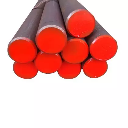
SCM440 Alloy Steel
SCM440 is medium carbon chromium molybdenum alloy steel, which is an alloy steel containing chromium and molybdenum. It has the advantages of stable composition, low harmful elements, high steel purity, small decarburization layer and few surface defects. It is easy to be spheroidized and has low cold cracking rate. It is usually hardened and tempered. The ultimate tensile strength is 850-1000 MPa. This material achieves a very good balance between strength, toughness and wear resistance. The chromium content of the alloy provides good hardness permeability, and the molybdenum element imparts average hardness and high strength.SCM440 reacts well in heat treatment and it is easy to process under heat treatment conditions. This material provides many desirable properties such as good strength and wear resistance, excellent toughness, good ductility and resistance to high-temperature stresses.
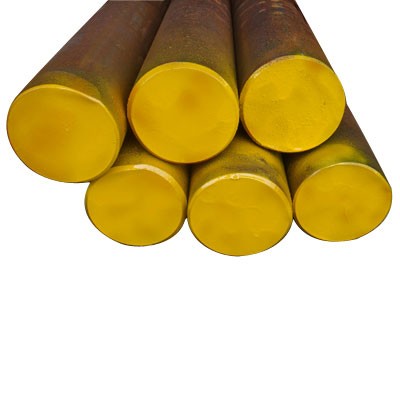
S45C Medium Carbon Steel
Applications requiring strength and impact resistance of the component, because of its high carbon content, therefore, have a higher tensile strength, ductility and wear resistance, but is not suitable for welding or forming.This steel grade can be supplied in many standard shapes, including round, square, hexagonal, and plate. It generally applicative used in nuts and bolts, axles, rollers, springs, wires, wheel frames, rods, engine parts, stamping dies, hammers, lock washers/lock pin gaskets, turbine rotors, railway tracks, cylinder sleeves, hand tools, screws, railway wheels, gears, garden shears, etc.

SUJ2 High Carbon Bearing Steel
Equivalent Grades: GB GCr15, JIS SUJ2, AISI 52100, DIN 100Cr6 (1.3505). SUJ2 has the great properties of bearings, such as wear resistance, toughness, hardness. Its workability and anti-fatigue strength are excellent as well. SUJ2 is widely used for the manufacture of plastic molds, ball bearings, steel ball, ball, bushings, shafts, guide rods, guide pins and other mechanical parts.